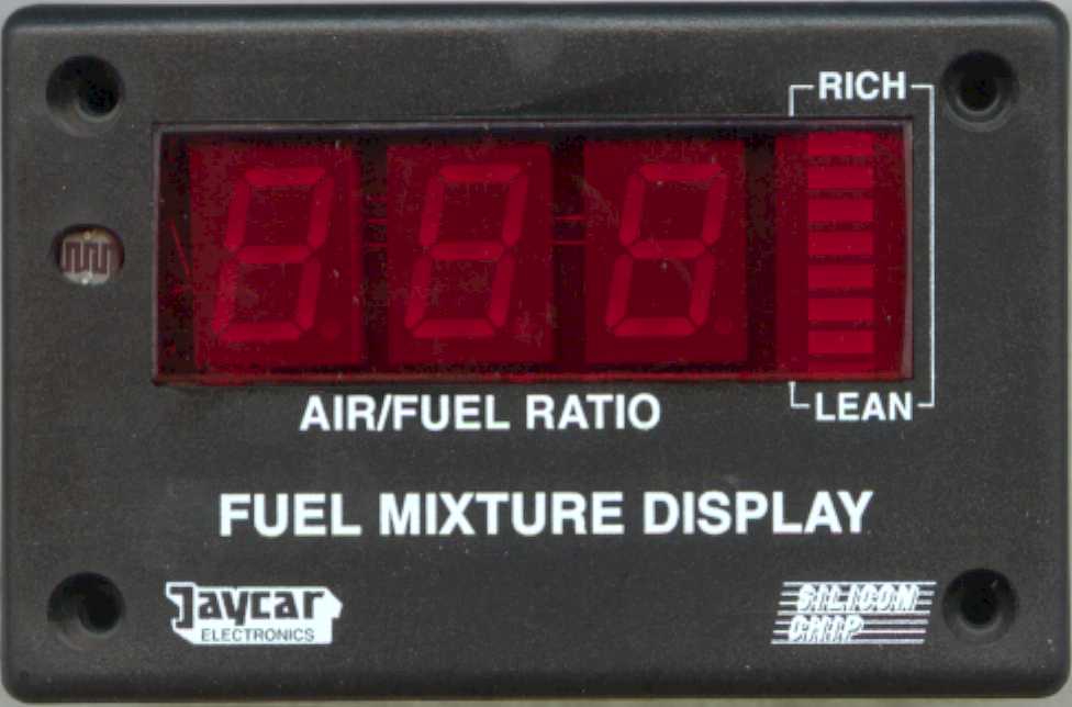
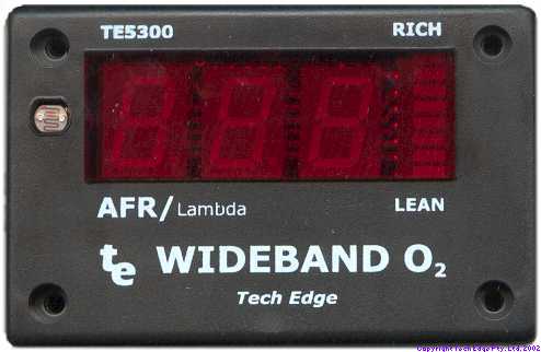
The images show the first Jaycar supplied TE-5300 kit (left) and our first TE-5301.
click on images to enlarged
TE-WB (v1.5) | Oz DIY-WB (v1.0) | TE-5301 | Wideband FMD | Silicon Chip FMD
This document is an introduction to the Wideband Fuel Mixture Display (FMD). We modified the original Silicon Chip Fuel Mixture Display (that used a narrowband sensor) for use as a display for the DIY-WB wideband oxygen sensor controller. After first publishing how to modify the Jaycar KC-5300, we got Jaycar to make up the kits for us and we called them the TE-5300 display. These units were quite successful but we wanted them to be easier to build, so we created the improved TE-5301 display.
This rest of this document describes how the 5300/5301 display works with the DIY-WB unit.
|
|
The images show the first Jaycar supplied TE-5300 kit (left) and our first TE-5301. |
|
|
click on images to enlarged |
||
|
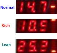
The three regions of operation are shown at right. A normal operating value (of 14.7 in this case) is shown as three digits. A rich condition is shown as 10. followed by an equals or less than symbol (=<). A lean condition is shown as 25. followed by a greater than or equals symbol (>=). Note: display is operating in dot mode. Other software changes are to:
The major changes have to do with how the dot and bar mode display intervals have been altered. |
 |
|
Dot mode displays 48 unique LED configurations with a difference of 0.2 AFR between steps, from 10.0 to 19.6 AFR. Either one single LED is fully lit, or two LEDs are lit with a varying intensity, giving the impression the LEDs move slowly upwards as the display shows a richer mixture. The single centre LED is lit for AFRs between 14.6 and 14.7. |
 |
 |
Bar mode displays just 8 different LED configurations with a chunky difference of 1.6 AFR between modes. It does have the advantage of easily seeing how far away from stoic you are by comparing the total width of the lit bars. |
The startup display now shows four important items (it was originally blank)
|
These options are (refer to the kit's instruction on how to enable them):
Refer to the diagram at right showing which LEDs relate to which mode. The default configuration is normal mode, displaying AFR with a 13 step Dot display. |
 |
Lambda mode uses a different lookup table to convert the A/D value from the sensor into a different display value. Lambda is simply the ratio of current AFR to AFR at stoic. For petrol this is commonly calculated as AFR/14.7 (although strictly it depends on the fuel, different fuels have different values for the AFR at stoic).
AFR |
10 | 11 | 12 | 13 | 14 |
14.7 |
15 | 16 | 17 | 18 | 19 |
20 | 21 | 22 | 23 | 24 | 25 |
LAMBDA |
0.68 | 0.75 | 0.82 | 0.88 | 0.95 |
1.00 |
1.02 | 1.09 | 1.16 | 1.22 | 1.29 |
1.36 | 1.43 | 1.50 | 1.57 | 1.63 | 1.70 |
mixture |
rich |
stoic |
lean |
||||||||||||||
In Lambda mode the rich range is always shown with a 0 in the left display position. Lean is shown with a 1. This makes it easy to see immediately if a rich or lean condition exists.
|
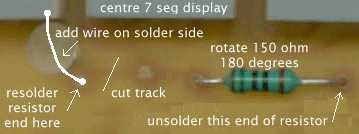
The actual changes to the PCB are simply to move the decimal point from its fixed position between the middle and the right digits, to between the left and middle digits. This is done by unsoldering the right end of the 150 ohm resistor on the display PCB, and resoldering it to the now vacant hole close to the left seven segment digit. The trace on the solder side should be cut with a suitable blade, and a wire run from the resistor's pad to the left display's unconnected pad (this is the pad closest to the dimmer pot's adjustment hole - look at the pad on the first display that the resistor was connected to if you're unsure). Also make sure you route the wire away from the large hole so that the dimmer pot on the processor PCB can still be adjusted when it is all assembled. |
|
The calibration procedure is similar to that described in the construction manual. The processor PCB is first wired temporarily with R2 - 1.8 k ohm, on the solder side of the PCB. The display will now show the SENSOR INPUT voltage in volts x 10, or alternatively, an out of range condition. You'll see either Lo, a value between 14.0 and 30.8 (representing 1.400 through 3.088 Volts), or Hi.
The calibration mode display actually shows 3 1/2 digits, the 1/2 digit is the dot/bar display, and is interpreted using the image at right (note that 0 is blank). However, as the firmware A/D converter is accurate to only 8 mVolts, the dot/bar display will give the appearance of "jumping all over the place" as it displays (say) 14.00 -> 14.08 -> 14.16, etc. - the dot/bar will jump from [blank] -> 8 -> 6, etc.
 A suitable voltage source for calibration can be obtained from an external 20 or 50 k ohm potentiometer
wired across a couple of fresh 1.5 volt batteries (which will show at least 1.6 Volts).
An accurate DVM measures the voltage input to the FMD unit (note: leave the meter connected during
calibration to ensure the test voltage is not influenced by the meter itself).
If you have a multi turn pot, then setting the test voltage becomes easier, although this is not essential.
A suitable voltage source for calibration can be obtained from an external 20 or 50 k ohm potentiometer
wired across a couple of fresh 1.5 volt batteries (which will show at least 1.6 Volts).
An accurate DVM measures the voltage input to the FMD unit (note: leave the meter connected during
calibration to ensure the test voltage is not influenced by the meter itself).
If you have a multi turn pot, then setting the test voltage becomes easier, although this is not essential.
The FMD unit is calibrated first at a minimum input voltage of 1.400 Volts (1400 mV) by adjusting R3, which is the new 5 k ohm potentiometer (VR3 = OFFSET) on the display PCB. The display should read 14.0 and the dot/bar should be blank. Ideally, the OFFSET pot should be set to almost display Lo as this will be closest to 1400 mV.
For the other end of the range, it is calibrated at a maximum input voltage of 3.000 Volts by adjusting the 250 k ohm potentiometer (VR2 = SPAN) on the processor PCB. This is done through a hole in the display PCB which is closest to the bottom left corner. The display should read 30.0 and the dot/bar should be blank. Ideally, the SPAN pot should be set to almost display 29.9 as this will be closest to 3000 mV.
This procedure should be repeated as each adjustment affects the other slightly. A quick check at other points in the displayed range of 1.40 to 3.08 can be made, but remember the DVM you use may have some linearity errors as well as the FMD circuit. The two displayed voltages should track such that the rightmost FMD digit is never off by more than one from the DVM's corresponding displayed value.
As with all kits, there are variations in the components supplied. We note that some people have reported being unable to set the lower calibration limit of 14.00 with 1.4 Volts across the sensor input, this can be "cured" (assuming there are no construction errors) by either replacing the 3.3 k resistor connected to VR3 with a larger value (say 6.8 k) or by replacing VR3 with the 20 k pot in the kit (though this will make adjustments to VR3 a little more "touchy").
The modified software may be made available in source form if copyright details relating to the original DIY-WB licencing agreement can be resolved, but at present the software will be made available only:
This software is copyright © 2001 Tech Edge Pty. Ltd. and I reserve the right to refuse any individual or organisation the supply of this software for whatever reason. In general the software will be made freely available if you want to use the FMD with the DIY-WB kit and you are doing this for your own personal non profit use. If you are a commercial organisation, then it may be possible for you to licence the software from Tech Edge Pty. Ltd for your own purposes. We can modify the software or the hardware design, and will do so at out normal consultancy rates.
As this software is supplied for free, there is absolutely no warranty either expressed or implied. You must decide for yourself as to the suitability of this kit for use with any other device.
Use of an air-fuel meter for tuning purposes represents a potential hazard to the safe operation of your vehicle. Use of any display device within a moving vehicle present a safety hazard. Be warned you should consider having an assistant when using this device.

Assembler/Disassembler | 1227808 ECM | 8192 Baud ALDL | 160 Baud ALDL
Last updated 23 December 2002 (links)
Statistics by
www.digits.com
Shows approximate unique hits since 03 November 2001.
This document is Copyright © Tech Edge 2001 and
contains reference to material that is Copyright © Silicon Chip.
Previous |
Home |
Feedback |
Copyright