TE-5300 - Wideband Fuel Mixture Display
TE-WB (v1.5)
| Oz DIY-WB (v1.0)
| TE-5301
| Wideband FMD
| Silicon Chip FMD
|
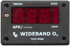
Updated 5301 Unit now available
This document describes the original Jaycar KC-5300 display that was modified
and sold by us as the TE-5300 display.
Tech Edge now sells the TE-5301 wideband display
(shown at left)
which is functionally identical
(and uses the same firmware) but comes with double sided PCBs and some extra features.
You can use the information in the following paragraphs to modify your existing KC-5300 for use with
the DIY-WB unit or another wideband sensor interface unit.
 Order a 5301 display kit from us at Tech Edge.
|
|
A suitable display for the DIY-WB unit is described here.
It uses a modified Silicon Chip Fuel Mixture Display
kit (the FMD unit). The standard unit features:
- 3 Digit LED readout plus bargraph.
- Display auto-dims at night.
- Calibrated for Bosch LSM-11.
The modified unit features:
- Calibrated for NTK sensor and DIY-WB (1.4 - 3.1 Volts input).
- From 10.1 to around 25.5 AFR (petrol, stoic = 14.7).
- Optional Lambda calibration built into software.
- 8 step bar or 48 step one/two dot operation.
- Optional RS232 output by adding three resistors.
The Silicon Chip September and October 2000 issue
features the original article about the FMD unit
that is available as a complete kit (with case), or a set of two PCBs
(prices correct @ 31 Oct 01) from:
|
The Jaycar KC-5300
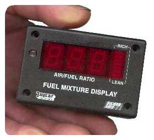
Enlarged image (39 kb)
|
Modifications to the FMD kit
As well as the basic modifications described here, we have
added RS232 output using just three extra resistors (and a connector).
As mentioned, the FMD kit is
described here.
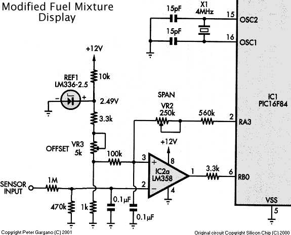
The modified circuit below should be compared with the
original circuit.
The input circuitry has been changed to handle the voltage range of 1.4
to 3.1 Volts, rather than 0.0 to 1.1 for the Bosch LSM-11. This requires
a new value for one of the presets (20k -> 5k) and a couple of 5% 1/4W
resistor changes too.
For your convenience we have included a component overlay for the two 5300 PCBs
showing the location of the three control pots and the three option resistors R1, R2, & R3.
The display, when used with the DIY-WB unit, is most accurate in the rich end
of the range (AFR 10:1) and easily gives 0.1 AFR accuracy (which is thus limited by the
accuracy of the WB unit itself). At the AFR 25:1 end of the range, the accuracy is about
0.2 AFR, again limited by the accuracy of the WB output.
The original software for the FMD kit is available as
zipped source form or
zipped hex
from Silicon Chip's web site.
How the WB-FMD works
The input from the NTK sensor is via a 1M and 470 k ohm resistor divider
network. This converts the 1.4 -> 3.1 Volts input range into approximately 0.45 -> 0.99 Volts
at pin 2 of the comparator IC2a. The capacitor across the 470 k resistor smooths
rapid fluctuations in the WB output and stabilises the digital display.
The original charge pump circuit has been removed and replaced by a simpler +2.49 Volt
reference that is divided by the 3.3 k resistor, the 5 k OFFSET preset, and the 1 k resistor
to produce a voltage that will balance the divided WB voltage of 0.45 at the low duty cycle
end of the PWM A/D converter's range.
At the high PWM range, the resistor in series with the
250 k ohm SPAN preset has been changed to 560 k ohm.
Changes to the software involved modifying the calibration display to show a voltage
from between 1400 and 3088 mV for the A/D count between 19 and 230. The actual circuit
now measures 8 mVolts between counts rather than the 5 mV for the LSM-11 sensor.
Tables for the bar and dot display have been compressed and use the AFR value in
the lookup process rather than the raw A/D count. Lambda mode simply uses a different
lookup table (this used to be the propane option selected with R3).
Detailed Changes to the PCB
The Jaycar KC-5300 kit comes with very complete construction details including a copy of the
two Silicon Chip articles describing it. Especially good is the black laser cut and professionally
silk-screened panel with red perspex lens that is easily assembled with glue.
See also component overlay for these two 5300 PCBs.
|
This is the processor PCB showing the 16F84A MicroChip processor and the LM358 acting as
a comparator and LDR buffer. The changes are to the bottom left area around the two blue preset pots.
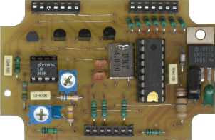
Enlarged and annotated image (40 kb)
***
Back of this same PCB ***
|
This is the display PCB that sits atop the processor PCB.
The changes are simple and require a couple of links to be use in place of a bunch
of components, the re-orientation of the voltage reference, and some resistor changes.
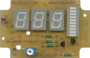
Enlarged and annotated image (30 kb)
***
Back of this same PCB ***
|
The instructions optimistically suggest 3 hours to complete the kit,
which is probably correct if you've already made one or two.
In addition to the reprogrammed PIC firmware (or a copy of the HEX file to program yourself), you'll need:
- 470 k ohm 1/4 W (5% is okay).
- 560 k ohm 1/4 W (5% is okay).
- 5 k ohm miniature preset potentiometer.
- removed 3.3 k and 10 k resistors are reused.
|
Note: that these parts are supplied in the KC-5300 kit when ordered from Tech Edge.
|
Software Changes
|
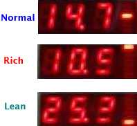
The three regions of operation are shown at right.
A normal operating value (of 14.7 in this case) is shown as three digits.
A rich condition is shown as 10. followed by an
equals or less than symbol (=<).
A lean condition is shown as 25. followed by a
greater than or equals symbol (>=). Note: display is operating in dot mode.
Other software changes are to:
- Make more efficient use of table space to allow the addition of the Lambda display mode.
- Redesign for more modularity for possible future upgrades.
- Version and mode information displayed on startup.
- Better calibration capability for DIY-WB output range.
The major changes have to do with how the dot and bar mode display intervals have been altered.
|
|
|
Dot mode displays 48 unique LED configurations with a difference of 0.2 AFR between steps,
from 10.0 to 19.6 AFR. Either one single LED is fully lit, or two LEDs are lit
with a varying intensity, giving the impression the LEDs move slowly upwards as the
display shows a richer mixture. The single centre LED is lit for AFRs between 14.6 and 14.7.
|

|
|
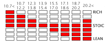
Bar mode displays just 8 different LED configurations with a chunky difference of 1.6 AFR between modes.
It does have the advantage of easily seeing how far away from stoic you are by comparing the total width of the lit
bars.
|
The startup display now shows four important items (it was originally blank)
- Tech Edge abbreviated logo in 7 segment format tEc. This shows for about half a second.
- The software version number as nm.c
where n is the major software rev. and
m is the minor software revision.
This also shows for about half a second.
- The c is the Tech Edge © copyright symbol.
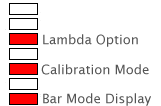
- During this time the bar display shows which of the three options have been wired (or switched) on.
|
These options are (refer to the kit's instruction on how to enable them):
- Dot or Bar mode (R1, installed = bar mode)
- Normal or calibration (also called Volt) mode (R2, installed = calibration mode)
- AFR or Lambda mode (R3, installed = Lambda mode)
Refer to the diagram at right showing which LEDs relate to which mode.
The default configuration is normal mode, displaying AFR with a 13 step Dot display.
|
|
Lambda Mode - Changes
Lambda mode uses a different lookup table to convert the A/D value from the sensor into a different
display value. Lambda is simply the ratio of current AFR to AFR at stoic. For petrol this is commonly
calculated as AFR/14.7 (although strictly it depends on the fuel, different fuels have different
values for the AFR at stoic).
AFR |
10 | 11 | 12 | 13 | 14 |
14.7 |
15 | 16 | 17 | 18 | 19 |
20 | 21 | 22 | 23 | 24 | 25 |
LAMBDA |
0.68 | 0.75 | 0.82 | 0.88 | 0.95 |
1.00 |
1.02 | 1.09 | 1.16 | 1.22 | 1.29 |
1.36 | 1.43 | 1.50 | 1.57 | 1.63 | 1.70 |
mixture |
rich |
stoic |
lean |
In Lambda mode the rich range is always shown with a 0 in the left display position.
Lean is shown with a 1. This makes it easy to see immediately if a rich
or lean condition exists.
|
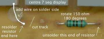
The actual changes to the PCB are simply to move the decimal point from its fixed position
between the middle and the right digits, to between the left and middle digits.
This is done by unsoldering the right end of the 150 ohm resistor on the display PCB,
and resoldering it to the now vacant hole close to the left seven segment digit.
The trace on the solder side should be cut with a suitable blade, and a wire run
from the resistor's pad to the left display's unconnected pad
(this is the pad closest to the dimmer pot's adjustment hole - look at the pad on the first display
that the resistor was connected to if you're unsure). Also make sure you route the wire away from the
large hole so that the dimmer pot on the processor PCB can still be adjusted when it is all assembled.
|
|
New Calibration Procedure
The calibration procedure is similar to that described in the construction manual.
The processor PCB is first wired temporarily with
R2 -1.8 k ohm, on the solder side of the CPU PCB.
The display will now show the SENSOR INPUT voltage in volts x 10, or alternatively,
an out of range condition. You'll see either Lo, a value between
14.0 and 30.8
(representing 1.400 through 3.088 Volts), or Hi.
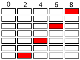
The calibration mode display actually shows 3 1/2 digits, the 1/2 digit
is the dot/bar display, and is interpreted using the image at right (note that 0 is blank).
However, as the firmware A/D converter is accurate to only 8 mVolts,
the dot/bar display will give the appearance of "jumping all over the place" as it
displays (say) 14.00 -> 14.08 -> 14.16, etc.
- the dot/bar will jump from [blank] -> 8 -> 6, etc.
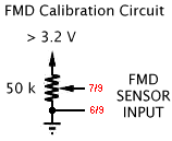 A suitable voltage source for calibration can be obtained from an external 20 or 50 k ohm potentiometer
wired across a couple of fresh 1.5 volt batteries (which will show at least 1.6 Volts).
An accurate DVM measures the voltage input to the FMD unit (note: leave the meter connected during
calibration to ensure the test voltage is not influenced by the meter itself).
If you have a multi turn pot, then setting the test voltage becomes easier, although this is not essential.
The FMD unit is calibrated first at a minimum input voltage of 1.400 Volts
(1400 mV) by adjusting R3, which is the new 5 k ohm potentiometer (VR3 = OFFSET)
on the display PCB. The display should read 14.0 and the dot/bar should be blank.
Ideally, the OFFSET pot should be set to almost display Lo as this will be closest to 1400 mV.
For the other end of the range, it is calibrated at a maximum input voltage of 3.000 Volts
by adjusting the 250 k ohm potentiometer (VR2 = SPAN) on the processor PCB.
This is done through a hole in the display PCB which is closest to the bottom left corner.
The display should read 30.0 and the dot/bar should be blank.
Ideally, the SPAN pot should be set to almost display 29.9 as this will be closest to 3000 mV.
This procedure should be repeated as each adjustment affects the other slightly.
A quick check at other points in the displayed range of 1.40 to 3.08 can be made, but remember
the DVM you use may have some linearity errors as well as the FMD circuit. The two
displayed voltages should track such that the rightmost FMD digit is never off by more than one
from the DVM's corresponding displayed value.
Trouble Shooting (27 January 2002)
As with all kits, there are variations in the components supplied. We note that
some people have reported being unable to set the lower calibration limit of 14.00 with 1.4 Volts
across the sensor input, this can be "cured" (assuming there are no construction errors) by
either replacing the 3.3 k resistor connected to VR3 with a larger value (say 6.8 k) or
by replacing VR3 with the 20 k pot in the kit (though this will make adjustments to VR3 a little more "touchy").
Obtaining the Software
The modified software may be made available in source form if copyright
details relating to the original
DIY-WB licencing agreement
can be resolved, but at present the software will be made available only:
- as a preprogrammed PIC chip for AU$25.
- as a preprogrammed PIC chip when a KC-5300 is
ordered through Tech Edge Pty. Ltd.
- as a HEX file that can be used to program a blank 16F84A PIC.
Requests for the hex file should be directed to
peter@techedge.com.au with a note that you will not use the software for commercial gain.
- I will program your own PIC for free if a brand new fully functioning 16F84A is
sent to me
along with a stamped self addressed return envelope (in Australia), or with the equivalent of US$3.00 to
cover postage and packing if from outside Australia. Ensure your package will not be damaged in transit
and you must supply a mailing label with your address.
This software is copyright © 2001 Tech Edge Pty. Ltd. and I reserve the right to refuse any
individual or organisation the supply of this software for whatever reason. In general the software
will be made freely available if you want to use the FMD with the DIY-WB kit and you are doing this
for your own personal non profit use. If you are a commercial organisation, then it may be possible
for you to licence the software from Tech Edge Pty. Ltd
for your own purposes.
We can modify the software or the hardware design, and will do so at out normal consultancy rates.
Warranty & Warnings
As this software is supplied for free, there is absolutely no warranty
either expressed or implied. You must decide for yourself as to the suitability of this kit for use
with any other device.
Use of an air-fuel meter for tuning purposes represents a potential hazard to the safe operation
of your vehicle.
Use of any display device within a moving vehicle present a safety hazard.
Be warned you should consider having an assistant when using this device.

Assembler/Disassembler |
1227808 ECM |
8192 Baud ALDL |
160 Baud ALDL
Last updated 11th June 2003 (links)
Statistics by
 www.digits.com
Shows approximate unique hits since 03 November 2001.
This document is Copyright © Tech Edge 2001 and
contains reference to material that is Copyright © Silicon Chip.
Previous |
Home |
Feedback |
Copyright

![]() Order a 5301 display kit from us at Tech Edge.
Order a 5301 display kit from us at Tech Edge.


 A suitable voltage source for calibration can be obtained from an external 20 or 50 k ohm potentiometer
wired across a couple of fresh 1.5 volt batteries (which will show at least 1.6 Volts).
An accurate DVM measures the voltage input to the FMD unit (note: leave the meter connected during
calibration to ensure the test voltage is not influenced by the meter itself).
If you have a multi turn pot, then setting the test voltage becomes easier, although this is not essential.
