
Further, and more recently written, 160 baud information can be be found here.
Many GM ECUs used the 160 baud format. These same ECU can also be found on some Australian Nissans, Daewoos, etc.
Any specific information shown below (eg. oscilloscope traces) relates to the author's 1990 VN 3.8L V6
Holden Commodore (described as a "VN" below) using an ECU with GM/Delco part number
1227808
(often referred to as an '808, or '7808)
We have attempted to make information in this document as generic as possible and have omitted physical details such as a description of the different ALDL connectors. Note: 8192 baud ALDL info can be found here.
Some early US ECU equipped vehicles, and Australian VN/VP Commodores, came with 12 Volt levels where the ALDL data output pin is connected to the CEL (Check Engine Lamp) or SES (Service Engine Soon) lamp. Later US models came with 5 Volt (often described erroneously as TTL) levels, and the SES lamp was connected to the ECU via a different circuit. If you have a 12 volt signal then you can use the simple 160 baud interface, otherwise you'll need to make the universal 160/8192 baud interface (more expensive, but more useful too).
I believe that all 12 Volt ALDL data streams will flash the SES/CE lamp (at 160 baud) when set to 160 baud ALDL (diagnostic) mode, and 5 Volt models don't do this (to be conformed!). All models will flash the SES/CE lamp when set to "flashing error code" mode.
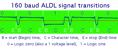
The 160 baud (also called bps, or bits per second) data stream is sent as a continuous stream of single data bits. Each bit, as viewed at ALDL connector (pin E on the VN), is made up of a number of signal transitions within a single bit time of 6.25 mSec.
All voltages described below are measured relative to the vehicle's ground (considered to be at 0 Volts). For 12 Volt ALDL data (connected to the vehicles CE/SES lamp) The lamp will go on when the ECU pulls the ALDL data pin low (to 0 Volts). When the ALDL data pin is high, the CE lamp is off, this is the normal state of the CE lamp and data pin. When the ALDL mode is first entered, the ECU will pull the ALDL data pin low, and the CEL will come on for a short period.
For 5 Volt ALDL data the CE/SES lamp is independantly operated, and may not flash when the ECU sends ALDL data.

Each data bit starts as a rising edge of the ALDL data stream (shown at T0 and at T4 in the diagram). After a small delay (T0 to T1) called the start time, the line is driven to the value of the data bit to be sent. For a logic 1 level this means the voltage level will be remain high. For a logic 0 level the line will be driven to a low voltage level.
At time T2, between 1.5-2.3 mSec into the character time, the data level is guaranteed to be stable and should be sampled here. At T3, the end of the character time, the signal line is driven low (or remains low for a logic 0). The interval T3 to T4, called the stop time, is a minimum of 0.5 mSec. At time T4 the process starts again for the next data bit.
The period T0 to T4, called a bit time should be exactly 6.25 mSec. thus there are 1000/6.25 or exactly
160 bits transmitted per second. A bit per second is called a baud (after Baudot, a developer of the teletype)
 Although I have not found a definitive specification for the individual times T0 to T4, they can be observed on real units.
As measured from the above signal, the following intervals are calculated for the VN
(although, in reality, the ECU memcal program actually determines these times):
Although I have not found a definitive specification for the individual times T0 to T4, they can be observed on real units.
As measured from the above signal, the following intervals are calculated for the VN
(although, in reality, the ECU memcal program actually determines these times):
The easiest way to determine if a 0 or 1 bit is being transmitted is to measure the time interval between negative going transitions (ie. the end of the start time) and then the next positive going transition's (ie. the start of the stop time). A method for doing this is described on this site.
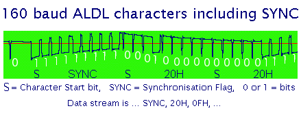
Data bytes (8 bits) are transmitted with the most significant bit (MSB) first. A leading 0 logic level start bit (indicated as the P bit in the photo) is added to delimit successive bytes. This gives a total of 9 bits per transmitted byte. The screen shot here shows 3 groupings of 9 data bits (the waving signal is due to the measurement technique - a sound card based oscilloscope).
The first character is a SYNC character (described below) followed by the character 20H (000100000) and 0FH (000001111).
A unique 9 bit combination of characters is used to begin each new grouping of data bytes. This grouping is called a data frame and begins with a SYNC (or synchronisation) character made up of a logic 1 start bit and 8 logic 1 bits. The screen shot above shows the SYNC character as 111111111 (note the preceeding short inter-frame delay). This combination of 9 ones cannot occur within the data part of a frame as each normal start bit is a 0 and at most we could expect to see 8 ones (a FFH character) both followed and preceeded by a 0 start bit.
GM has not defined a standard "frame data format" for the ALDL information. Rather, each ECU, and in fact, each specific ECU's memcal program, determines what ECU/memcal data is present in the ALDL data stream. Thus a '808 with a VN memcal may have different ALDL data than the same ECU used on a Nissan Pulsar. Additionally, automatic, manual and airconditioned variants may have slightly different data interpretations.
As an exercise, we have completed an interpretation of the VN Holden Commodore's ALDL data stream.
The 160 baud ALDL data stream is NOT a standard format that can be read directly into a standard PC. However the data rate is relatively slow and it can be fed into a PC's serial port and interpreted even on a machine as slow as the original IBM XT.
One simple scheme, used by the author, is to feed the data into a single transistor level converter that is connected to the PC's serial port. Rather than use the traditional Rx (or receive) line, the CTS signal line receives the data stream. The corresponding software measures the time intervals between signal transitions on the CTS line (using the PC's 8253/8254 counter/timer) and regenerates the ALDL data bytes for display on the PCs screen. Note however that this scheme is prone to noise, and the newer serial RX data approach described here should be understood.
Further technical information on building a PC based ALDL interface is available from this site.