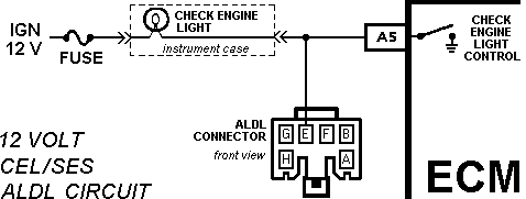
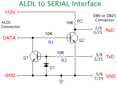
If you have a 12 volt ALDL signal, and you don't intend to read any other ALDL data streams, you can use a simple 12 Volt 160 baud interface to read the data.
General Motor's 160 Baud ALDL Data Stream can be read with a standard serial port running at a rate of from 1600 baud or above. How this works is described in this article. GM's 160 baud ALDL data stream is described here too, and we also have Simple software (or more complex software) that can then be used to read the ALDL data stream.

We have attempted to make information in this document as generic as possible and have omitted physical details such as a description of the different ALDL connectors. Note: 8192 baud ALDL info can be found here.
GM does not publish public information on their ALDL protocol, nor ALDL data formats for different ECUs. The following information is applicable to GM vehicles worldwide although Australian cars may be specifically described.

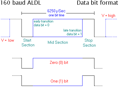
The 160 baud (also called bps, or bits per second) data stream is sent as a continuous stream of single data bits. Each bit is made up of a high to low, and a low to high voltage transition within a time of 6.25 mSec (or 6250 microseconds - written as uSec).
|
All voltages described below are measured relative to the vehicle's ground (considered to be at 0 Volts). For 12 Volt ALDL data (connected to the vehicles CEL/SES lamp) The lamp will go on when the ECU pulls the ALDL data pin low (to 0 Volts). When the ALDL data pin is high, the lamp is off, this is the normal state of the lamp and data pin. Each data bit starts as a falling edge of the ALDL data stream - positioned in the diagram at the left most end of the 6250 uSec measuring bar. After a small delay (the Start Section in the diagram), if the bit to be sent is a zero (0) the data line will return to a high level. If the line stays low for a longer period then it represents a one (1) bit. To complete a bit, the data line remains high for a period represented by the Stop Section in the diagram. Both 0 and 1 bits, shown separately in the two smaller waveforms, take exactly the same bit time - amounting to 6250 uSec. There are therefore 1,000,000/6250 or 160 bits transmitted per second. |
Bit per second (BPS) are commonly called baud (after Baudot, a developer of the teletype) and this is why the signal is commonly called a 160 baud ALDL data stream.
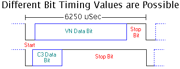
Different ECU types may use different Start, Data, and Stop times. The total should always come close to 6250 uSec. I have measured the times for a 1227808 ECU running a standard Holden VN calibration (ASBX in this case), and these are shown below. Remember that a high data section represents a 0, and a low represents a 1 bit. In the diagrams the data sections are coloured blue.
|
|
|||||||||||||||||||
I have also been told that [ref 1] early generation C3 ECUs had very different start and stop bit timing (and they ran at a baud rate of 159 rather than exactly 160). These variations are clearly shown in the waveforms above.
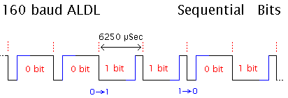
Here is a diagram showing successive data bits of a 160 baud ALDL stream. The voltage variations can make it confusing to identify bit boundaries (shown as red dotted lines).
|
You can see four distinctive variations of the waveform. Both continuous 1 and 0 bits produce a "toothed" waveform (either one way up, or the other). A 0 to 1 bit transition looks "sparse", and a 1 to 0 transition looks "busy". The actual "look" of the waveform will be influenced by the start and stop timing variations discussed above. |
|
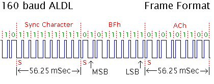
This diagram shows two data characters (0BFh and 0ACh) following a special sequence of bits known as a sync character. Each character is made up of 9 bits, and takes 9 x 6.25 mSec = 56.25 mSec. A normal data character begins with a leading 0 start bit and then the 8 bits of the character follow (8 bits are also called a byte). The byte is transmitted with the most significant bit (MSB) sent first. |
|
A sync (or synchronisation) character is just a normal 0FFh byte but with a leading start bit value of 1 rather than a a normal character's 0 start bit. This sequence of nine (9) one bits only ever occur for a sync character, and can be used to uniquely identify it.
The sync character is used to begin a frame of data characters. The 0FFh (with start bit of 1) is not part of the data, but identifies or delimits the start and end of the data.
GM has not defined a standard "frame data format" for ALDL information. Rather, each ECU, and in fact, each specific ECU's memcal program, determines what data is present in the ALDL data stream. A typical ALDL frame may contain 20 bytes of data including a sync flag, giving a total of 21 x 9 bits = 189 bits per frame, and a transmission time of 189 x 6250 uSec = 1.18 seconds. The ECU may also insert a short delay between each frame.
Serial data has a universal RS232 format that can be recognised by a standard serial port as would be found in a PC, a MAC or a hand held device. The RS232 voltage levels on the connecting cable between devices is inverted (and probably level shifted too) so that a 1 logic level sent from a transmitter is represented by a negative voltage (or zero), and a zero logic level by a positive voltage. Signal inversion and conditioning may be performed by an RS232 transmitter chip such as the DS-1488 (160 kbyte PDF data sheet). Data reception and inversion may be handled by an RS232 receiver chip such as the DS-1489 (200 kbyte PDF data sheet).

Receivers like the DS-1489 can handle a low voltage of 0, rather that a fully RS232 compliant negative voltage level. Note: the idle RS232 line condition is represented by a negative (or zero) voltage. So, a start bit must be a positive RS232 level. A stop bit represents the RS232 line returning to the IDLE voltage.
|
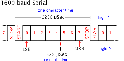
This diagram represents a single RS232 character at logic levels into or out of a UART (Universal Asynchronous Receiver/Transmitter. Remember that RS232 levels will be inverted. Time is increasing from left to right. At a bit (or baud) rate of 1600, each bit of the serial data is 625 uSec wide. There is a logic 0 start bit and a logic 1 stop bit to delimit the data. The mid part of the serial data is divided into 8 bits that may be either zero or 1. The UART interprets the first bit received (left most in diagram) as the LSB (Least Significant Bit) of the 8 bit character. The MSB (Most Significant Bit) is transmitted just before the stop bit. The complete character, including the start and stop framing bits takes 6.25 milliseconds to transmit. The next character transmitted may begin its start bit right after the previous stop bit is sent, allowing up to 160 characters per second to be sent. |
|
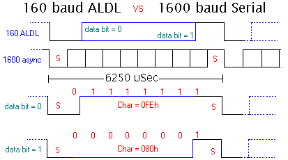
The top part of this diagram shows a single 160 baud 0 bit or a 1 ALDL data bit. The data portion of the bit will be a positive voltage for a logic 0, or a zero voltage for a logic 1, and is represented by the area between the ALDL start (left) and stop (right) parts. The second waveform shows how the data stream would be interpreted by a UART set to receive at 1600 baud. The last two waveforms show what the UART would see for an ALDL o and 1 bit (remember the MSB RS232 bit is sent last). Comparing, we see that serial data bits 1 through 6 correspond to the mid part of the ALDL data bit. We could choose to look at serial data bit 4 - its value is the inverse value of the ALDL data bit. It is a simple matter to convert each received serial character into a 0 or 1 bit, and then assemble each successive 9 bits into a single 8 bit ALDL data byte. |
|
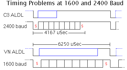
The diagram above is for a fictitious 160 baud data stream. As mentioned, timing of the start, mid, and stop parts of each ALDL data bits varies between ECM applications. The C3 data stream has a shorter start bit compared to the VN data stream. 1600 baud serial data bits are 625 uSec wide, but the C3 start bit, at 351 uSec wide, is in danger of being ignored by some UARTs. Additionally, 1600 baud is a non-standard rate that some software may have difficulty producing (although this is no problem for the hardware of a standard PC)
|
This diagram illustrates VN and C3 data compared with both 1600 and 2400 baud serial data formats. Note that the 2400 baud start bit fits reasonably well into the C3's start bit. But also note that the VN's data bit does not mesh with the 2400 baud stop bit - A high ALDL data bit works, but a low data bit will produce a serial stop bit that will be low rather than high. This will cause most UARTs to report a framing error. This is not a fatal situation as long as the software is aware of the problem, and is coded to recover.
Other RS232 baud rates may be appropriate for other ECMs, but it illustrates the use of a standard UART to interpret the ALDL data stream. |
As mentioned, RS232 signals are inverted compared to the bit streams seen by a UART. A GM ECM produces a data signal at either a 12 Volt (SES/CEL style level) or 5 volt level (TTL/CMOS levels) that must be inverted and converted to RS232. One simple scheme is to feed the ALDL data into a single transistor level converter that inverts the data to produce a pseudo RS232 level (varies between 12 Volts and 0). This is connected to the receive data line of a serial device to be processed by a UART.
|
As noted above, standard RS232 signals varies between a negative voltage less than about 3 volts and a positive voltage grater than 3 volts. Most RS232 receivers however will work quite satisfactorily if the voltage varies between 0 volts and some figure greater than 4 volts. The circuit [ref 2] shown here serves two functions:
Note that Q1, D1 and R3 are not necessary if only 160 baud ALDL data is to be read. However, if the faster (and bi-directional) 8192 baud ALDL data stream is to be read, then the complete circuit as shown here is required. |
|
Here are some links to 160 baud ALDL software that uses the serial port techniques described in this article.
The original version of this interface connected to the RS232 CTS signal line and the corresponding software measured the time intervals between signal transitions (using the PC's 8253/8254 counter/timer). The problem with this approach was that extra effort was required to extract the data bytes, and the scheme did not lend itself to operation under Windows NT/2000. As well, the UART Rx logic actively rejects noise that can disrupt orderly reception of data on the CTS pin. Long RS232 leads, and electrically noisey vehicles add to this problem.
Further technical information on building a PC based ALDL interface is available from this site.
Assembler/Disassembler | 1227808 ECM | 8192 Baud ALDL | Wide Band O2 meter
Statistics by www.digits.com
Approx. unique hits since 09 May 2001.

Last updated 9 Feb 2010 (images) | Tell me about broken links