Here are notes on one way to construct your Oz DIY-WB PCB. last updated 13 July 2002.
We have also added the finishing off the WB with the CX kit section
that you should also read before beginning construction.
Measure all resistors, preferably with a DVM, before soldering
(they have been marked in k ohms or possibly with an omega symbol,
so 0.1 is 100 ohms).
Orient them all the same way to aid reading them visually after you solder them in.
Some component legs will need to be bent carefully with small needle nosed pliers.
Avoid stressing the bodies of all components.
CON1 Connector or Circular Connector Wiring
The parts kit is now supplied without a header, on the basis that you'll
wire direct to the 8 pin circular connector in the CX (completion) kit, and that you'll
wire the power/GND lead direct to the PCB. The following two paragraphs are for
installations that will not use the CX kit.
A 10 pin male header and female connector (Jaycar HM3440 & HM3450) must first
be cut down to a 7 and 2 pin connector. Use a hacksaw on the 8th (unused) part of
each, leaving two parts. The base of the male header must be "relieved" to make space
for components close by - use a bench grinder to make it look like the image here.
The "left" end grind needs to be wider than the right grind. The two way connector
doesn't need to be adjusted, just cleaned up before soldering.
Each header must be carefully eased into the PCB before soldering. Make sure the
raised plastic locating side of the header is away from the components.
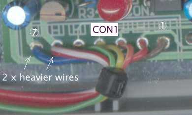
If you are using the CX kit then the following connections should be made AFTER the
PCB has been loaded. Connect 5 wires (brown 1, red 2, orange 3,
yellow 4, green 5), of the flat cables direct to CON1 pins 1 thru' 5.
The heavier wires (for the heater) go to CON1 pins 6 and 7.
A cable tie is used to pre-stress the 7 wires going to CON1.
This operation minimises the possibility of metal fatigue that has the potential to
make the direct wiring to the PCB fail in time.
Low Current Power Supply
The following components
can be soldered in (working from left to right) C15
(0.1 uF, bend its legs with needle nosed pliers if necessary), U4 the 78L08 regulator
(note: U4's silk screened outline is rotated 180°
to its correct orientation), C13 (10 uf), C12 (22/25 uF), R33 (10 ohms),
and R28 & R29 (both 10 k), and D7 (the 1.5 KE 33A diode) but be careful not to
stress the black plastic body too much.
The female 2 pin connector can be crimped (and/or soldered) to a black wire (GND)
to pin 2, and a red wire to pin 1. These two wires should be taken to a bench
power supply with a current limit of say 1 amp. Nothing should light up on power up.
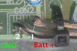
If you are not using the CON2 header (you have a CX kit) then wire direct to the
PCB and relieve the solder connection with a cable tie through the left hand DB9 hole,
as shown in the image at right.
Note that heavy duty figure 8 wire is used with the black trace
on the left hand (note - this is GND of CON2) side. You can also use a short piece of RED heatshrink over the
other end (right side) of the power/GND cable to help you remind which side is positive (the non-trace side).
A voltage of 8.0 Volts should be measured at pin 14 of the U3 socket
(designated as U3p14), this is beside the R7 label.
Important: Always lever out the plastic retainer on the PCB header (with your thumb)
and the 2 and 7 way plugs will easily slide in and out of the headers
without stressing the PCB.
U2 and the Virtual Ground
The remaining three 0.1 uF block monolithic (blue with 104M marking) capacitors,
C1, C3, C5 are mounted next. If necessary, the legs of the capacitors should be bent
with needle nose pliers (to ensure the body of the component is not stressed)
so the capacitors fit into the 0.1" holes provided.
Sockets can be used for the three 14 pin ICs, U1, U2 and U3
(sockets are now supplied in the parts kit).
note: U2's silk screened outline is rotated 180°
from its correct orientation.
An LM324 should be mounted in the U2 position.
These components are shown here.
When power is applied, U2p7 should be at 4.0 Volts.
Thermal Ip Enable
The long leg of the single LED diode is the anode and this goes to the +ve side of
things to produce light.
The right leg is the long leg - also check that the flat on the LED's base is on the left.
Solder the LED (the domed top of the LED should be 20 mm above the PCB), then U5 (the 6 pin opto isolator - the dot indicates pin 1 - away from CON1), then
in a clockwise order, R34 (1 k), Q3 (2N3906), R36 (100 k), R37 (2.2 k) & R31 (47 k).
With power connected the LED should be OFF.
Now loosely inserted (but do not solder) a 1 k resistor between the anode and cathode of D5
- the left and middle pins (test here on the image.
Note:
D5's T0-92 outline is NOT marked on the silkscreen, but it is below R39.
The LED should light up with the resistor in place.
A voltage of over 400 mV should be measure between U5p6 and GND when the LED is ON
(resistor in place), and close to 0 with the LED off.
Heater Regulator
C9 and C10 (both 10 uF) can be soldered with C9's -ve to the right, and C10's -ve at the top.
The previous test should still work.
Now add, from left to right, R35 (1 k), R39 (4.7 k) and R38 (1.5 k)
but don't add D5 (LM431) yet (it is shown in the image at left).
Also add the large 1 ohm 5 Watt resistor (see image(s) below)
so that it can be mounted on a heatsink when the circuit is working,
and add U7 (LM317, or LM1086 if you want lower drop-out operation)
so that its numbering can be seen from the component side.
The regulator can be inserted from either the top or bottom through the PCB.
You don't need the heatsink for the regulator yet.
To test the regulator, use a temporary resistor (1 k) inserted between the left hand hole of C8
and the right hand hole of R30 (ie. between the LM317's ADJ terminal and ground - see image taken
after C8 was added at a later stage).
With 12 Volt power, measures the voltage at CON1p7 (H+) and CON1p6 (GND or H-) -
without the temporary 1 k resistor, it should be less than a volt lower than the power supply voltage,
with the resistor it will be about 2.5 Volts.
The actual voltage should (according to the LM317 data sheet's explanation of its operation)
go down to ~ 1.25(1 + Rtest/R35) where R35 is 1 k and Rtest is also 1 k.
In this case the H+ (measured at CON1 pin 7, should be ~2.50 Volts.
I measured 2.55 V with the temporary 1 k resistor,
and 4.10 V with a 2.2 k - calc = 1.25(1+2.2) = ~4.0,
and 7.40 V with a 4.7 k - calc = 1.25(1+4.7) = ~7.13.
These values are all normal and show that (with no load)
the regulator is regulating.
Regulator Heatsink, etc.
A pre-drilled heatsink is supplied in the CX kit. The following text assumes you are
making your own heatsink.
We need to test that the regulator can handle the simulated power load of the sensor's heater
and must temporarily use the heatsink clipped to the TO-220 regulator.
In practice, you need to have a heatsink area at least as large as the PCB,
preferably larger.
An extra hole should be drilled in the PCB to mount it to the heatsink
and prevent it from shorting to the PCB.
This hole is drilled into the enclosed (top) part of the R in the silk screen text of R40.
The hole will be just far enough away from the PCB's power trace
(ensure the bolt also has an insulated washer if there is any chance of shorting).
See a further image of this below.
It is very important that the Al plate is bolted to the PCB with stand-off nuts
so that no part of the Al shorts to the PCB components.
Also, TO-220 insulating hardware (supplied in the kit) must be used to
ensure the TO-220's body is insulated from the Al.
Make sure the regulator plastic body is not stressed when bolted.
A 12 Volt 5 W lamp (an auto tail lamp) can be wired to the connector
CON1p7 and CON1p6 (the sensor's heater).
When power is applied, and with a temporary 4.7 k resistor as noted above (and a 12 Volt supply),
the lamp should come on dimly. Changing the temporary resistor to 1 k will turn the lamp
almost off (removing the resistor turns it ON).
At this stage we have checked that the regulator is regulating in a very basic sense.
Before we finally attached the heatsink, we soldered Q1 (2N3904), Q2 (2N3906) and R9 (27 k),
R1 (10 k) as well as C7 (10 uF, -ve to the side of R9). D1 and D2 (bands to lower side)
should be positioned by very carefully bending one lead before soldering so that their
body touches the corresponding transistor - this is supposed to make the Ip drive more
thermally stable.
Note in the image at right you can see we have used the low drop-out LM1086 rather
than the LM317 - the 1086 will allow you to run the sensor with a lower battery voltage.
Regulating the Heater through Vout
We have not been controlling the heater (the lamp) yet.
The LM431 (D5) turns on sharply when its REF input voltage exceeds 2.5 Volts.
The R38/R39 voltage divider sets the H+ turn-on voltage at 2.5*(4.7+1.5)/(1.5) = 10.33 Volts.
When it turns ON it drives the D5/D6 junction to GND and turns on Q3 which in turn enables
the LED and opto-isolator, and hence the control signal to activate the Ip control circuitry.
Add D5 (LM431, flat to top) as shown in a previous image (Heater Regulator section),
also add D4 (IN4148, band to CON1).
Most 1 Amp power supplies will provide enough drive current to turn on the LED when
VBatt reaches 12 Volts.
With the above setup (using an LM1086), I found that at VBatt of about 12.0 Volts
the LED just started to glow,
and at 12.2 Volts it had lit brightly. At VBatt of 14.4 Volts, VHeater was 10.36 Volts,
demonstrating that the heater voltage was being limited to ~10.4 Volts.
With an LM317, and a 5 Watt load (as above) the LED came on at about 0.5 Volts higher
(12.7 Volts).
Heater Soft Start
The remaining transistor Q4 (2N3906), R30 (47 k) and C8 (10 uF, -ve to the left) can be installed.
You will need to bend the legs of C8 as there is insufficient clearance between it and C9
(it should sit neatly between C9 and C10 after this operation).
Test the soft start operation by observing that the lamp now takes between 10 and 20 seconds to
get to maximum brightness. If not, check the polarity of the capacitor and orientation and sex
of the transistor (the silk screen is correct!).
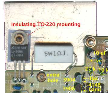
Trimming the Heater Current
If you have not already drilled a hole in the PCB for mounting the heatsink
(as noted above), do so now.
Leave the leads on the 6.8 ohm resistor long enough to allow the nut to be done
up on the mounting bolt without interference with the 6.8 ohm 1 Watt resistor.
The image shows three highlighted mounting points for the heatsink.
It also shows the LM317 (U7) soldered from the bottom of the PCB.
As noted above, R40 is an additional 1 Watt resistor in parallel with the 5 Watt 1 ohm resistor (R41).
It's value decreases the combined resistance between the ADJ and OUT terminals of the regulator.
The regulator tries to maintain 1.25 volts across ADJ and OUT. The maximum heater current
of 1.5 amps therefore requires a resistance of 1.25/1.5 = .83 ohms.
A 6.8 ohm resistor in parallel with the 1 ohm resistor will have a resistance of 1/(1/1 + 1/6.8) = 0.872 ohms
giving a max current of 1.25/0.872 = 1.43 Amps. Latest kits are supplied with a 6.8 ohm 1 W resistor for R40,
although you could try a 5.6 ohm resistor that would give a calculated Imax of 1.47.
Be aware that the 1 ohm resistor has a tolerance of 5%, which means it may be as low as 0.95 ohms, in which
case a 6.8 ohm resistor in parallel will have a combined resistance of 0.834 ohms, and an Imax of almost
exactly 1.5 Amps.
Completing the Ip Off circuit
The following components should be added - C11 (3.3 uF), R16 (100 k), R18 (68 k), R21 (22 k),
and R17 (100 k). Also, add U3 the 4066 (assuming you've used a socket).
With everything connected, the R18/R21 junction (right end of resistors)
should remain at a low voltage until the LED comes on,
and then should rise to close to 5 Volts.
Note that the LED need only be fairly dim for the Ip enable to be activated.
Now add R1 & R2 (10 k) and R3 (100 k).
Measure the voltage at the junction of R1 and
R2 (right end of R1, left of R2) and confirm it is very close to 6.0 Volts
(this will be 2.0 Volts with respect to VGnd).
Now add U1 (LM324) and measure the voltage at pin 14 of U1.
With no sensor (you don't even need a dummy lamp load) it should be at
around 7 Volts (I measured 6.8).
If a 10 k resistor is temporarily connected between pins 1 and 2 of CON1,
pin 14 U1 should now drop to close to 0 Volts (and enabling the Ip drive).
The Ip enable is designed to be off until a valid Vs signal from the sensor is active.
Vs Ref Circuit
The Vs/Ip feedback loop compares the Vs signal against a 450 mVolt reference voltage
generated by D8 and buffered by U2A.
Note: The following signals are measured relative to Virtual Ground (VGnd)
which is obtained from CON1p2.
Now add R25 (10 k), R26 (22 k), R27 (10 k), R32 (82 k), and D8 (LM385-1.2).
The VsRef signal at U2p3 should be close to 450 mV (0.45 Volts).
When measured after the op-amp has buffered the signal, and introduce a small bias voltage,
you should see a few milliVolts higher
(say 453 mV at U2p1).
Ip Sense, Vout Buffer & Vs Feedback Circuit
There is no simple way to test the operation of these circuits individually.
So I suggest you add the remaining components to the PCB (excluding the
optional parts not supplied - ie. R42, R43, U8, and U9) and check
carefully that all your soldering is good with no bridged joints
(check carefully all the TO-92 devices that have very closely spaced pads).
If you have not already done so, wire up
CON1 pin 1 (red wire) pin 2 (black) and pin 3 (white).
Only a light gauge wire is required for pins 1 through 5 of CON1
as these connections are to the NTK sensor's sense cell (pin 1 = Vs) and pump cell (pin 3 = Ip)
and the common Vs/Ip (pin 2).
To test, connect the Vs and Ip lines together (red and white) and wire
a 100 ohm resistor (now supplied in the kit) between this point and Vs/Ip Gnd (black).
Attach a meter set to the 2 Volt range connected across the 100 ohm resistor.
Attach power and you should see very close to zero volts until the LED comes
on at which point the meter should read 450 mV or slightly higher.
Now measure Vout using the meter between Gnd
(a convenient point is the left end of D7 - the large black diode)
and CON3 pin 7 (this point is also the right hand pad of R42).
Vout should be around 3.85 to 3.89 Volts.
If you have not already done so, wire up
CON1 pin 4 (with say blue) and pin 5 (with say green)
- this will become the connection to the calibration resistor in the sensor's connector.
Now apply a short between these two pins (blue/green CON1) and note that
Vout should drop to between 3.30 and 3.34 Volts.
Completing Assembly
We now offer the CX (or completion) kit.
With all components assembled and working you can mount the PCB in a case.
You could also use something like a metal diecast box just slightly larger than
the PCB (say the Jaycar HB-5067 = 119 X 94 X 34 mm).
More info on construction soon - send me photos and extra information to include.
We appreciate your feedback on the content and any corrections necessary to this article.


