Previous | WideBand | Pre-Built | Kit | 1.5 Info | Technical | Wiring | Schematic | Construction | Software | 5301
![]() The following diagrams show how the TE-WB 1.5 is connected to the
the wideband sensor, 5301 display, and other devices including PDA, PC,
and input devices for logging.
Note the warning about using standard RS232 (including null modem)
cables connected directly to the WB unit's DB9 connector.
The following diagrams show how the TE-WB 1.5 is connected to the
the wideband sensor, 5301 display, and other devices including PDA, PC,
and input devices for logging.
Note the warning about using standard RS232 (including null modem)
cables connected directly to the WB unit's DB9 connector.
|
|
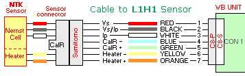
L1H1 Sensor CableThe cable to the L1H1 sensor is composed of 4 lightweight shielded wires with two used for Vs and Ip, two for the calibration resistor CalR (which is located in the Sumitomo connector body) and the 5th is the shield (Vs/Ip common). Two heavy duty conductors are used for the heater current Heater +/-. |
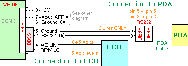
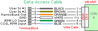
Data Access cable - Inputs & NB outThe 6 way terminal block connecting to the 5 pin circular connector is wired as shown. There are two analogue 0->5 Volt inputs (for MAP, TPS, etc. called User In #1 and #2), the narrowband output, and either the low voltage RPM input, or the higher voltage COIL RPM input. Note the ring on the circular connector connects to ground. |
|
|
|
Battery and GNDThe heavy duty battery (+12 V) and GND cable is permanently attached to the 1.5 WB unit. Protection is provided for shorts by a 3 Amp fuse and reverse polarity protection by a 6A schottky diode within the WB unit. The battery lead is distinguished by a RED heatshrink section on the connection end. |
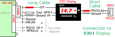
5301 DisplayThe 5301 display connects to the WB unit using its longer grey cable. Just three signals are used on the WB unit's DB9; 12 Volt (battery), GND, and Vout. The 5301 also has a short cable with a DB9-S that carries low speed RS232 with the encoded AFR generated by the display itself. Other signals on the DB9 are described below. Note the 5301 display's long cable terminates in a DB9-S (ie. female Socket). |
|
|
|
RS232, PC/Palm & ECU I/O
The other signals on the DB9 can be divided into an RS232 signal carrying logged data, linear wideband signal for possible connection to an ECU, and a low voltage RPM input signal that can be logged. Note that the RS232 signal is connected to a PDA using a cable with a DB9-P (ie. male Plug) that plugs into the PDA's RS232 serial adapter. Note also that pin 2 on the DB9-S socket at the WB unit end goes to pin 3 on the DB9-P plug at the PDA cable end. |
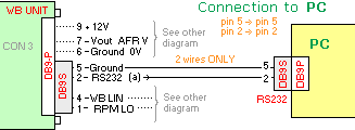
RS232 to PC - with DB9Just two pins (2 and 5) from the WB unit should be wired to a DB9-S for connection to a PC. A standard PC null modem cable will not work as there will be other wires on the cable that will interfere with the operation of the WB unit. Note that pin 2 is wired to pin 2 on either connector. |
|
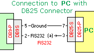
RS232 to PC - with DB25If you have a PC with a serial DB25-P (ie. with pins, a DB25-S socket will be a parallel interface for a printer) then you can use the connections show at right rather than the for the DB9. Note that when moving from the DB9 on a PC to the DB25 you swap pin 2 (RxD) for 3 and pin 5 (GND) for pin 7. |
|
|
|
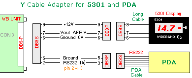
Y Cable Adapter for PDAA Y cable adapter can be made up to allow a PDA and the 5301 display to be simultaneously connected to the WB unit. |
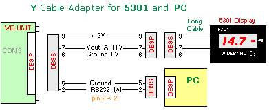
Y Cable Adapter for PCA Y cable adapter can be made up to allow a PDA and the 5301 display to be simultaneously connected to the WB unit. |
|
|
|
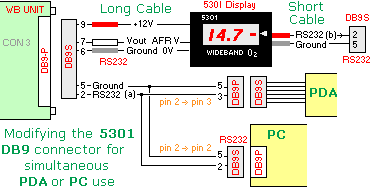
PC/PDA with 5301It is possible to modify the existing 5301's DB9-S to allow either a PC or a PDA to be connected to the WB unit while the 5301 is connected too. Note it may not be possible to drive both a PDA and a PC at the same time. Note also the PC use a DB9S with pin 2, and the PDA uses a DB9P with pin 3. |

Last updated 14 June 2003
created 30 March 2003
| Tell me about broken links
Previous
| Home
| Wideband
| Copyright